MaîtreAnchor TDoA
Stationary Indoor UWB Network Gateway / Base Station for TDoA & TWR Positioning (Model FM-MA-TDOA)
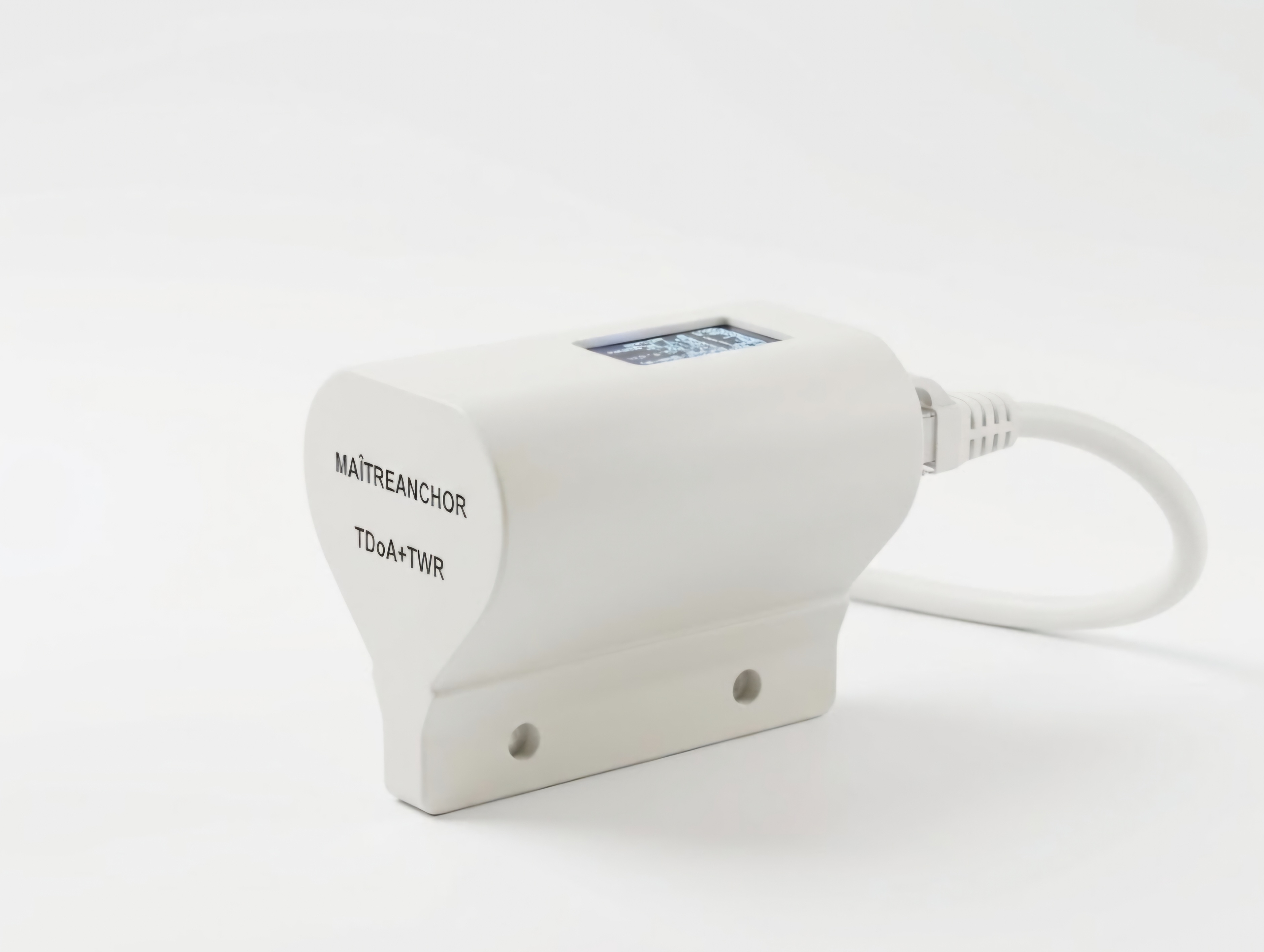
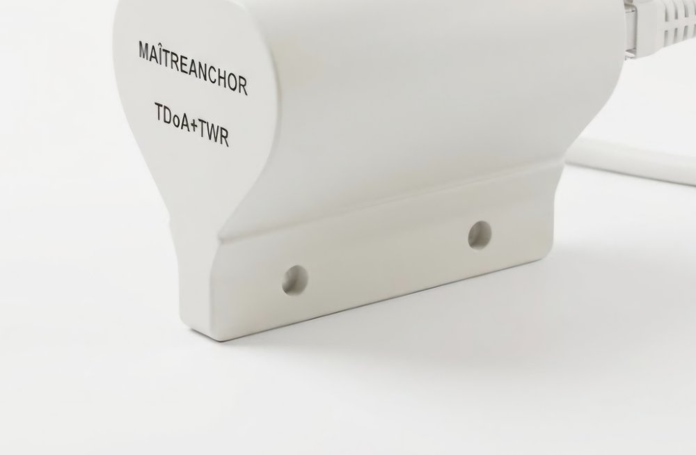 Mounting Flange with 2 × Ø4 mm Holes
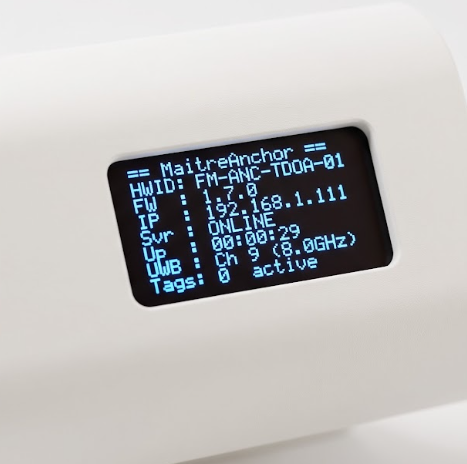 Integrated Diagnostic OLED Display
FM-MA-TDOA
UWB Ch 5 & Ch 9
Rx-Only / TDoA+TWR
86 × 46 × 38 mm • 68 g • ABS
Overview & Principle of Operation
MaîtreAnchor TDoA is a stationary indoor network gateway (base station) designed for industrial RTLS and smart building positioning systems. The anchor receives ultra-wideband blink packets from MaîtreBadge and MaîtreTag devices, performs hardware time-of-arrival timestamping (Time Difference of Arrival — TDoA, as well as Two-Way Ranging — TWR), and forwards aggregated telemetry to the positioning server over 2.4 GHz Wi-Fi or Ethernet.
- Receive-Only (Rx-Only) & TDoA+TWR Modes: Can operate strictly as a passive UWB receiver (zero UWB RF emission) or in wireless clock-synchronized TDoA+TWR mode.
- On-Site Diagnostics: Built-in OLED display shows network and server status, so installers can commission the anchor without a laptop.
- Flexible Power & Backhaul: 5 V USB Type-C power or optional PoE over Ethernet.
- Quick Installation: Side mounting flange for screw installation on walls, pillars, or overhead trusses.
Technical Parameters — MaîtreAnchor TDoA
| Parameter | Specification |
|---|---|
| Product Identification | |
| Model | FM-MA-TDOA |
| Radio Frequency (RF) Characteristics & Network | |
| UWB Interface (IEEE 802.15.4-2015 / 802.15.4z) | Operating frequencies: 6489.6 MHz (Channel 5) / 7987.2 MHz (Channel 9), 499.2 MHz bandwidth. Supports Rx-only passive reception mode (zero UWB emission) as well as wireless TDoA+TWR synchronization |
| Wi-Fi Network Interface | IEEE 802.11 b/g/n, 2412–2472 MHz, maximum output power (EIRP) ≤ 20 dBm (100 mW) |
| Ethernet Interface | Wired Ethernet, optional PoE (IEEE 802.3af/at) |
| Bluetooth Interface | Bluetooth Low Energy 5.0, 2402–2480 MHz, output power up to +4 dBm (2.5 mW) |
| Diagnostics & Power Supply | |
| Diagnostic Display | Integrated top-panel OLED display: model, HWID, IP address, server connection status, uptime, current UWB channel, and number of active tags |
| Power Supply | 5 V DC via USB Type-C (up to 250 mA, ≤ 1.25 W) or PoE (IEEE 802.3af/at, optional, ≤ 2.5 W) |
| Mechanical Parameters & Security | |
| Dimensions & Weight | 86 × 46 × 38 mm (including side mounting flange). Weight: 68 g |
| Enclosure | Impact-resistant ABS housing; side mounting flange with two Ø4 mm screw holes |
| Optional Encryption | When enabled, UWB STS (Scrambled Timestamp Sequence), Bluetooth, Wi-Fi, and Ethernet links are encrypted; can be disabled for non-cryptographic operation |
Device Mounting & Deployment Guidelines
1. Mounting Height & Line-of-Sight (LoS)
- Install anchors at a height of 2.5 to 5.5 m above floor level to maintain clear Line-of-Sight (LoS) to worn badges and asset tags.
- For over-the-air clock synchronization, keep the reference anchor of each cell in direct LoS of the other anchors, at a spacing of 10–35 m.
2. Cell Geometry (GDOP)
- Arrange anchors around the perimeter of the tracked zone with a cell aspect ratio no greater than 3:1 (square or near-square cells minimize Geometric Dilution of Precision).
- Avoid collinear anchor placement when 2D/3D TDoA localization is required.
3. Clearance & Mechanical Fastening
- Fasten the unit using the two Ø4 mm holes on the side mounting flange.
- Maintain at least 15–25 cm clearance from large metal girders or sheet-metal ducts to prevent near-field multipath distortion.
Planning a MaîtreAnchor TDoA Deployment?
Our engineers will prepare an anchor placement layout based on your facility floor plan.
Request Deployment Layout